Simplewire Flex+ QR Quick Start

Get a reliable first scan with Flex+ in 5–10 minutes

Use this guide at the electrical panel and go straight to the step-by-step instructions.

New to Flex+? Start with the video

See the workflow in 2 minutes

The video provides a quick overview of the unit, scanner and workflow.

  • Where Flex+ performs best in the installation.
  • How to use the scanner to confirm the signal and location.
  • Which setup choices usually determine whether the signal is stable.

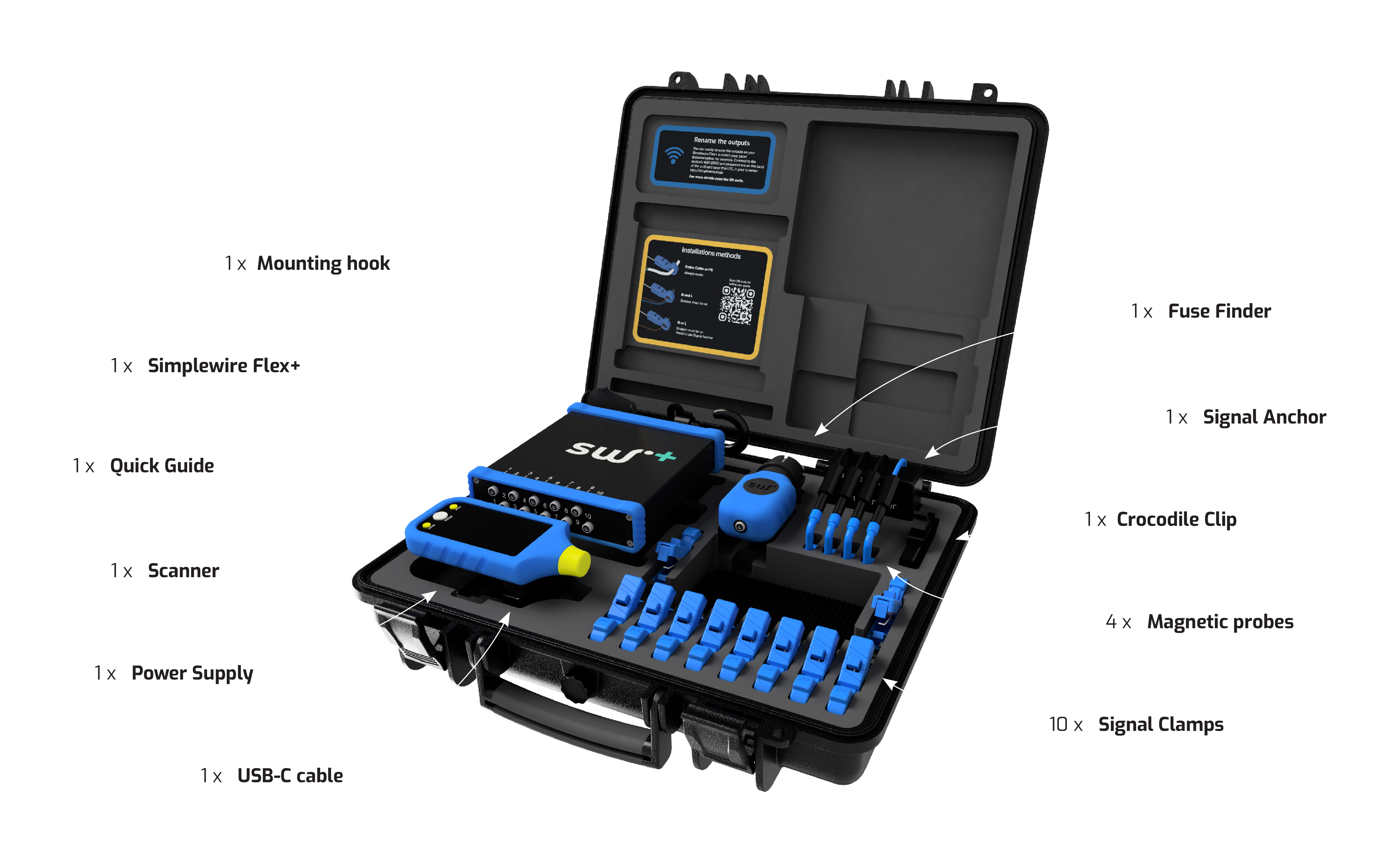
What is included in the case?

Open Flex+ case with the unit, scanner and accessories organised in the insert
The case contains standard equipment and additional accessories. You do not need everything to get started.

Quick start

Four steps to your first reliable scan

01

Switch on the devices

Press the power button on both the Flex+ unit and the scanner. A blue light and a short beep confirm that each device is ready.

Low battery

If a device beeps and flashes red, the battery level is too low for reliable operation. Charge it before continuing.
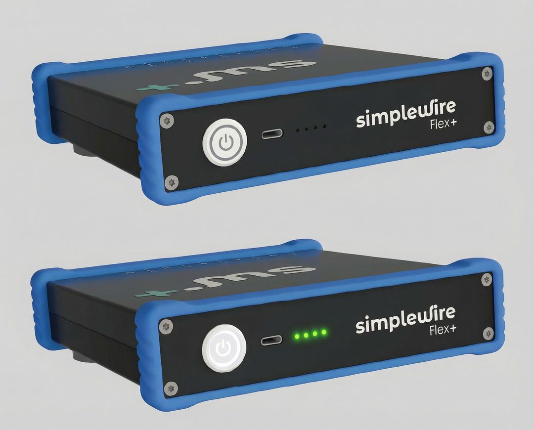
Close-up of the Flex+ unit showing the power button and status lights
02

Secure Flex+ in the electrical panel

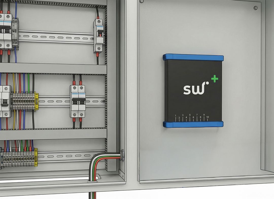
Mount the unit with the front facing outwards and the rear towards the electrical panel. Use the built-in magnets or mounting hook to keep it secure and the signal outputs within easy reach.

Check: the unit must not be loose or obstruct your work in the electrical panel.

Flex+ unit securely mounted in an electrical panel with the front facing outwards
03

Choose the correct signal-clamp configuration

This is the most important choice in the setup. Always start with the strongest method the installation allows, and only move to a weaker method when necessary.

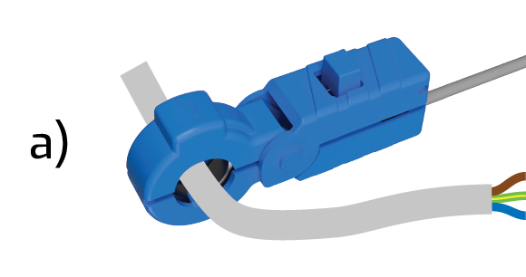
a) Entire cable

The preferred and most stable method. Always try this first.

Clamping method A with the signal clamp around the entire cable
See requirements and limitations
  • Place the signal clamp around the entire cable, including PE.
  • Always recommended when possible.
  • PE must have a proper earth connection.
  • A broken or floating PE can cause weak and unpredictable signals.

Shielded cables: place the signal clamp downstream of the shield's earth connection, after the point where the shield is earthed.

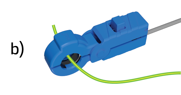
b) Protective earth (PE)

Reliable when PE has a proper earth connection. Use only when clamping the entire cable is not possible.

Clamping method B with the signal clamp around protective earth (PE)
See requirements and limitations
  • Place the signal clamp around PE only.
  • Use when clamping the entire cable is not possible.
  • PE must have a proper earth connection.
  • A broken or floating PE can cause weak and unpredictable signals.

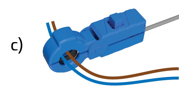
c) Phase and neutral together (L + N)

A strong method, but it does not work when the circuit breaker or switch is off.

Clamping method C with the signal clamp around phase and neutral together
See requirements and limitations
  • Place the signal clamp around N + L or N + L1–L3.
  • The next-best method when clamping the entire cable is not possible.
  • Signalling does not work when the circuit breaker or switch is off.

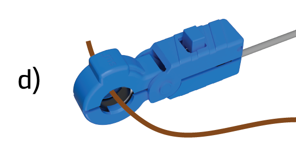
d) Phase only or neutral only

The weakest method. It requires Signal Anchor and is more sensitive to load and reference errors.

Clamping method D with the signal clamp around phase only or neutral only
See requirements and limitations
  • Using L only or N only is more prone to errors and may cause crosstalk or weak signals.
  • Signal Anchor must be used.
  • Signalling does not work when the circuit breaker or switch is off.
  • Loads above approximately 4 A can weaken the signal significantly. At 6 A, the signal may disappear completely.

What determines whether the method works

  • When clamping the entire cable or PE, PE must have a proper earth connection.
  • N + L and single-conductor methods do not work when the switch is off.
  • Phase-only or neutral-only measurements require Signal Anchor.
  • With a single conductor, loads above approximately 4 A can weaken the signal; at 6 A, it may disappear completely.

Read the limitations below.

04

Perform the first scan

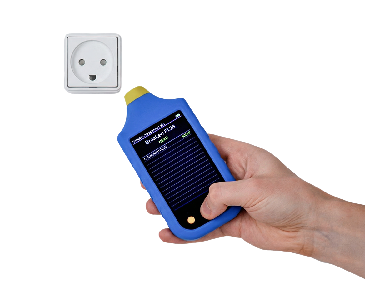
Place the yellow scanner tip against the object you want to check, then press and hold the metal button to start scanning.

Look for the strongest stable signal. If the reading is weak or unstable, check the reference setup, battery and measurement method.

Hand holding the Flex+ scanner against an installation during scanning

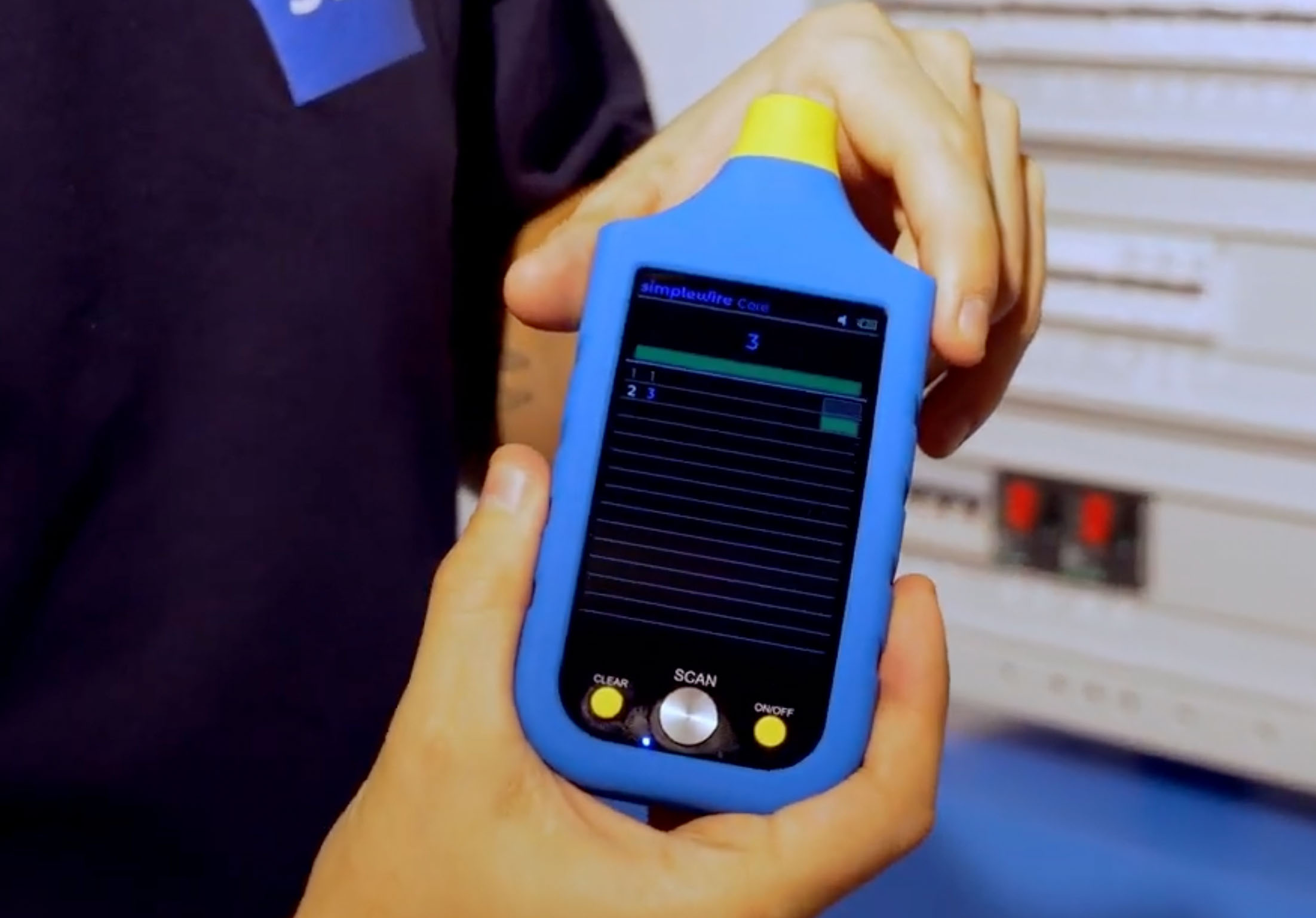
Scanner display

A clear signal appears as a prominent bar on the display. Use it to confirm that the scanner is close to the correct part of the installation.

Scanner display showing the signal-strength bar during scanning
How to read the signal

When a signal is detected, a signal bar appears. The stronger the reading, the closer the scanner tip is to the correct part of the installation.

Press the yellow button on the scanner to clear the scan history.

  • Always check the reference setup before changing the measurement method.
  • A low battery in either the unit or scanner makes the signal less stable.

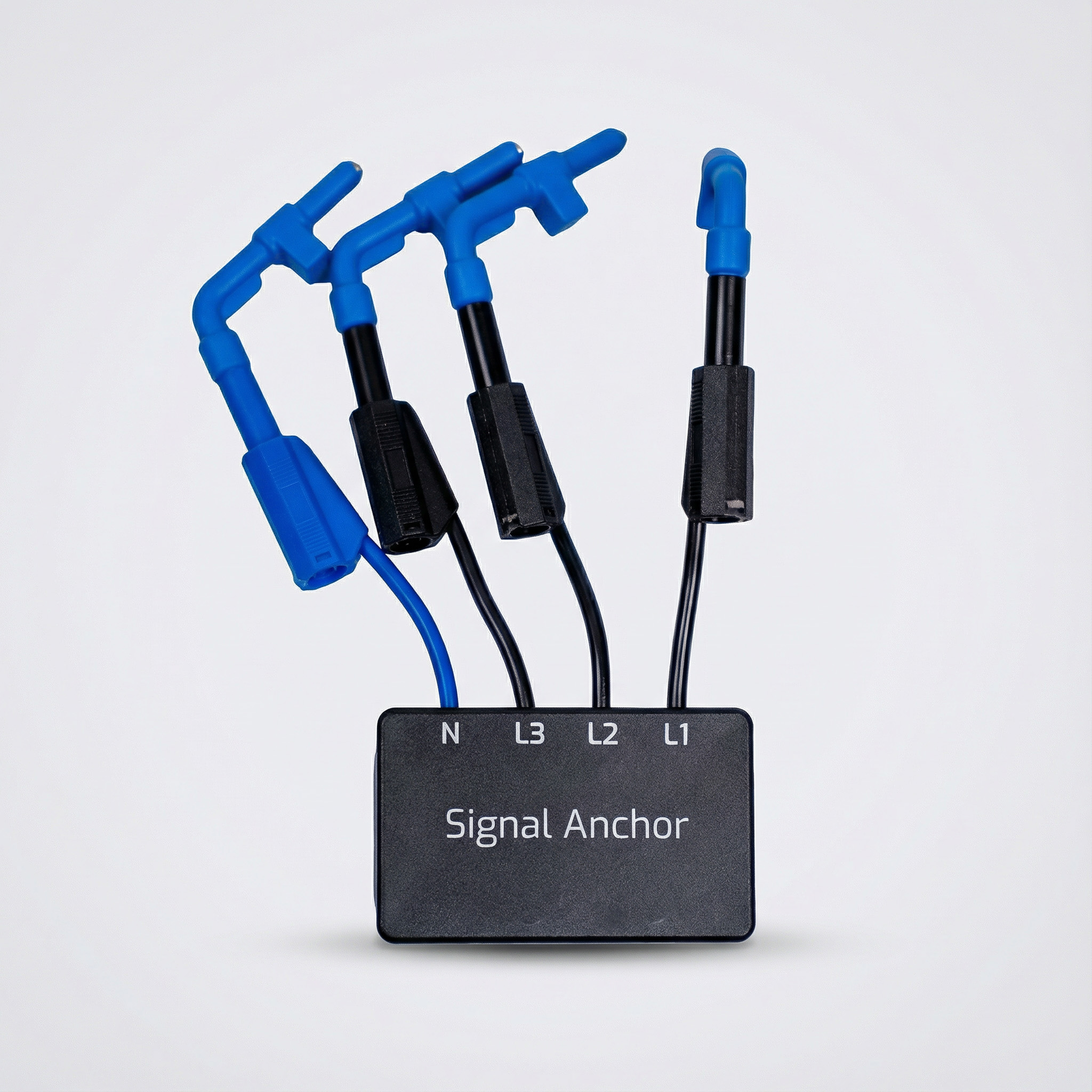
Signal Anchor

Signal Anchor

Use Signal Anchor when measuring phase only or neutral only.

Using Signal Anchor

  • Use Signal Anchor when measuring phase only or neutral only.
  • Connect neutral (N) and phases (L1–L3) as early in the electrical panel as possible to establish the reference.
  • Signalling does not work when the circuit breaker or switch is off.
  • Loads above approximately 4 A can weaken the signal significantly. At 6 A, the signal may disappear completely.
Simplewire Flex+ Signal Anchor for phase-only or neutral-only measurements

Recommended use

Requirements and limitations that affect the signal

If step 03 does not produce a stable result, check these key requirements, limitations and possible sources of error.

Intended use

  • Flex+ and Core are designed to transmit identification signals from sub-panels into the installation.
  • Other applications may work in practice, but they are not guaranteed.
  • Clamping the entire cable remains the preferred method whenever the installation allows it.

PE and screened cables

  • Methods 1 and 3 require PE with a proper earth connection. A broken or floating PE can cause weak and unpredictable signals.
  • When clamping the entire cable, PE must be included in the cable.
  • On screened cables, place the signal clamp downstream of the screen's earth connection.

When the signal becomes unpredictable

  • Earth loops matter: when clamping the entire cable or PE, the signal is only present where an earth loop is formed.
  • If a cable branches, sections outside the earth loop may appear to have no signal even though they are electrically connected.
  • Mixed N or L conductors between circuits cause unpredictable behaviour, and correct operation cannot be guaranteed.
  • The system is resistant to electrical noise, but in rare installations interference or earthed objects may shield the signal.

Other applications and Fuse Finder

  • Ethernet cables, main electrical panels, DC installations and control systems have been demonstrated in practice, but are not guaranteed.
  • Fuse Finder is designed to trace backwards through the installation, from socket to fuse.
  • Only scanning in the electrical panel is guaranteed. Scanning cables directly can be more difficult because magnetic fields may cancel each other out.
  • Signal spread in the electrical panel is normal. Use Delta mode to locate the strongest signal.

Technical specifications

Essential Flex+ specifications

Key specifications for the signal, batteries, operating environment and package contents. Use the table as a quick reference at the electrical panel.

10

numbered signal outputs in one unit.

95 kHz

On-Off Keying (OOK) active signal type.

8–16 cm

typical scanning range, depending on the environment and installation.

IP5X

for dry environments with some dust, but no exposure to water.

System and signal

System
Consists of
Simplewire Flex+ unit and compatible scanner.
Outputs / channels
10 numbered signal outputs.
Signal type
On-Off Keying (OOK).
Signal frequency
95 kHz.
Typical scanning range
8–16 cm, depending on the environment and installation.
Maximum current draw
6 A with N/L single-conductor induction.
Maximum loop impedance
5 ohm.

Power and charging

Battery
Flex+ battery
5200 mAh Li-ion.
Scanner battery
1850 mAh Li-poly.
Operating time
Approximately 10 hours for both Flex+ and the scanner.
Charging
USB-C.
Charging temperature
Charge at room temperature. The recommended range is 5°C to 40°C.

Environment and compliance

Environment
Operating temperature
-10°C to 40°C.
Ingress protection
IP5X for dry environments with some dust, but no water exposure.
Compliance
CE, RoHS and REACH.
WEEE
Must be handled in accordance with EU Directive 2012/19/EU.

Package contents and service

Package
Included as standard
1x Simplewire Flex+, 1x scanner, 1x USB-C cable, 1x mounting hook, 1x power supply and 1x quick guide.
Accessories
1x Fuse Finder, 10x signal clamps, 4x magnetic probes, 1x Signal Anchor and 1x crocodile clip.
Service / calibration
No scheduled servicing or calibration is required.

Troubleshooting

Spend 30 seconds on the right checks

No scan or no clear signal
  • Check that both Flex+ and the scanner are switched on.
  • Confirm that the batteries have sufficient charge.
  • Make sure the signal clamps are fully closed around the conductor.
  • Check whether you are measuring phase only or neutral only without Signal Anchor.
The signal is weak or unstable

First check that the clamp is on the correct conductor and that the reference setup matches the measurement method.

Then check whether PE has a proper earth connection, whether N or L is mixed between circuits, and whether earthed objects or electrical noise are shielding the signal.

I am measuring phase only or neutral only

Use Signal Anchor. Connect N and L1–L3 as early in the electrical panel as possible, then repeat the scan.

Remember that signalling does not work when the circuit breaker is off. A high load on the circuit may also weaken the signal.

I do not get a signal in every branch

When an earth loop is formed, the signal follows only the path containing that loop. Other branches may therefore appear to have no signal if the earth loop is in a different branch.

What should I know about Fuse Finder?

Fuse Finder is designed to trace backwards through the installation, from socket to fuse. Guaranteed scanning takes place in the electrical panel.

Scanning cables directly can be more difficult, and signal spillover within the electrical panel is normal. Use Delta mode to locate the strongest signal.

Contact support

If the problem continues after these checks, email support@simplewire.io.

Tell us how the clamps are connected, whether Signal Anchor is in use and whether the device indicates a low battery. This helps us assist you more quickly.

Common mistakes

The four most common causes of a failed first scan

Most initial problems have a small number of recognisable causes. Identifying them early saves time and prevents incorrect conclusions.

Signal

Incorrect reference

Phase-only or neutral-only measurements without Signal Anchor, PE without a proper earth connection, or mixed N/L conductors often produce unclear and unpredictable results.

Battery

Insufficient charge

A red flash or repeated beeps indicate that you should charge the device before continuing.

Environment

Moisture, noise or shielding

Flex+ is intended for dry environments only. In rare installations, electrical noise or earthed objects may also shield the signal.

Service

Unauthorised tampering

Do not open the device or attempt repairs yourself. This increases risk and may void the warranty.

Ready to continue

Did you find what you needed?

If you still need help, review the troubleshooting section above or contact support@simplewire.io.